PLEASE NOTE: This article has been archived. It first appeared on ProRec.com in November 1998, contributed by then Contributing Editor Jose-Maria Catena. We will not be making any updates to the article. Please visit the home page for our latest content. Thank you!
Frequency filters
A frequency filter modifies the amplitude response into a determined bandwidth. What we know in the audio world as an equalizer is a frequency filter. I won’t cover here a description of audio equalizers from a usage point of view, what surely you know well. If it is not so, you might want to read the series about equalizers from Lionel L. Dumond. What I’ll explain here are some basic properties of digital filters.
Filters change audio in two ways: by changing the amplitude vs. frequency, and by changing the pahse vs. frequency.
The amplitude response is represented by a graph where the X axis is the frequency and the Y axis the amplitude gain.
The phase response is represented by a graph where the X axis is the frequency and the Y axis is the phase.
There are two main kinds of digital filters: IIR (Infinite Impulse Response), and FIR (Finite Impulse Response).
IIR filters
An IIR filter is the mathematical representation of analog filters. The core is always a delay line where the output is fed-back to the input. Of course, there are many possible variations, but there are some common characteristics in all IIR filters:
– Smooth amplitude responses without unwanted discontinuities are possible.
– The phase response, like in their analog counterparts, can’t be flat, it always presents more or less phase shift, usually near the transition points.
– The parameters or coefficients used in the algorithm to make the wanted response are often easily computed from the type of data the user usually can provide. For example, for a parametric EQ, the user deals with center frequency, gain, and Q factor or bandwidth; for a low pass, with cutoff frequency and slope, and so on. And these are easily translated to the necessary filter parameters in the form of pole and zero vectors.
– Like analog filters, the wanted performance might require a configuration of several basic IIR filters. Then we speak about first order, second order, and so on based in the number of elements. An element can provide amplitude response slopes up to 6 dB per octave each. A second order filter can provide up to 12 dB/octave, a third order 18 dB/octave, and so on. That is, as more abrupt the amplitude response is, more elements (read higher order) are necessary.
– Due to the feedback, IIR filters can present lack of stability such auto-oscillation and ringing. Careful design and simulations on operating ranges are necessary, in special when extreme response curves are required.
– IIR filters require less computational power than FIR filters.
These characteristics make IIR filters the choice for typical audio equalizers.
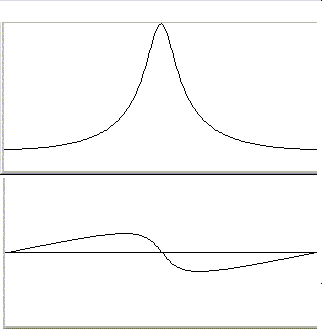
An example of the magnitude and phase responses of a typical IIR band-pass filter is:

FIR filters
A FIR filter has no counterpart in the analog world. It can only be represented or implemented in a numerical, purely mathematical form. It’s basically a delay line of length N (number of taps), where the output is the sum of products of each sample in the delay line by the corresponding coefficient in an array of the same length. It doesn’t employ feedback. More abrupt amplitude responses requires a larger N. Main characteristics are:
– The amplitude response is more or less irregular.
– The phase response is constant if the number of taps N is odd.
– The coefficients that determine the filter response are not directly derived from the required specifications. The most used method to compute these parameters is the Parks-McCellan algorithm, that converts response specifications including maximum allowable ripple into the parameters array.
– FIR filters are inherently stable. Due to the absence of feedback, there can’t be undesired side effects like auto-oscillation.
– FIR filters need usually more computational power than IIR filters. Basically, a multiplication and accumulation per tap.
These characteristics make FIR filters ideal to implement bandwidth limiters. Very steep slopes are possible, even in the range of thousands of dBs/octave.
An example of the magnitude response of a typical FIR low pass filter of 119 taps follows. Note that phase is not presented as it is flat, a characteristic of FIR filters with odd N. Note also the step transition from 0 dB to –100 dB in less than three semitones. This is a cut!
Digital vs. Analog filters
Digital IIR and FIR filters have been a real revolution, offering performance many orders of magnitude above analog filters, and doing even what would be absolutely impossible in the analog world. Analog filters can’t ever present constant phase like odd FIR filters. The higher analog filter order I have ever seen is 4th. Analog filters are based in components whose impedance changes with the frequency: capacitors and/or inductors. The impedance of a capacitor is half with twice the frequency, and the impedance of an inductor is twice when frequency doubles. This is the cause of the 6 dB/octave slope per element described for IIR filters, that are no more than the mathematical model of an analog filter.
Current technology has not been capable of producing real capacitors or inductors without large differences from the ideal models. It’s difficult to achieve value tolerances better than 10 %. Temperature stability and value drift over time aren’t good in capacitors. Many capacitors present very important series inductance, and the ones that doesn’t are of very low values. Inductors are affected by lack of linearity in cores. They have unwanted series resistance, parallel capacitance. The size constrains the practical value range, they are very susceptible to magnetic and electromagnetic noise, and they interact with each other when they are close. In definitive, is not possible in practice to even approach the 1% of the possibilities offered by DSP technology.
Sample Rate conversions
Discrete sample rate conversions must be always done with integer ratios, either down or up. That is, a 44K1 stream can be down sampled to 22K05, 11K025, …, or up sampled to 88K2, 176K4,…
The algorithm that does the down sampling is called decimator, and the one that does the up sampling is an interpolator.
When a fractional ratio conversion is required, it is achieved doing an interpolation to the minimum common multiplier of both rates, and then decimation to the final rate. If the minimum common multiplier is a very high rate, we might find a reasonable approximation that is “near” of an integer multiplier of both rates. But then, we will introduce some distortion, whose magnitude depends on the error with respect to the multipliers. This is the case with conversion between two of the well known standard rates and its derivatives used for audio: 44K1 and 48K. These values were chosen precisely because the difficulty to convert to each other without quality losses. It was imposed by the record industry to constrain unlimited piracy when DAT was introduced.
Whenever the sample rate is changed, the Nyquist frequency is changed (it’s half of the sample rate, do you remember). So, aliasing noise appears. To avoid that, the signal must be filtered before a decimation or after an interpolation to limit the bandwidth to the lowest of both Nyquist frequencies. For efficiency, the anti-aliasing filter is usually integrated with the decimator or interpolator. The best choice for the anti-aliasing filter is a nice odd FIR filter, what can do a perfect work without affecting phase. Many conversion programs are actually using IIR filters for this, and I believe that the only reasons are that programmers doing audio DSP software are often more familiarized with IIR or that IIR can be executed faster. The decimators in oversampling converters almost always employ FIR filters.
To guarantee absolute absence of alias noise, the low pass filter must present stop band attenuation in the order of the dynamic range. To avoid any alteration in the audible region, the pass band must extend beyond the audible bandwidth. The pass band ripple (amplitude variations) should be lower than 0.5 dB. A FIR filter can easily exceed all of these requirements.
Decimation
A decimator converts a stream to a lower sample rate which is in integer ratio with the original. The procedure is simple:
1) An anti-aliasing filter is first applied to the stream to remove the portion of the bandwidth that can’t be represented at the lower rate. As explained, anything above the final Nyquist must be removed.
2) N-1 of each N samples are removed, where N is the decimator ratio.
Interpolation
An interpolator converts a stream to a higher sample rate which is in integer ratio with the original. The procedure is:
1) Insert N-1 zero samples after each original sample, where N is the interpolator ratio.
2) Apply an anti-aliasing filter with cutoff frequency below the original Nyquist. To keep the amplitude, the filter must have a gain of N.
Fractional conversion
This method must be employed when the two rates aren’t one an integer multiple of the other. The conversion goes through an intermediate sample rate that must be the lowest integer multiple of both, that is, the minimum common multiple. We’ll call this intermediate rate I. If it’s very high, it could be not possible to implement in practice, and we must choose a rate that is close enough to integer multiples of both rates. There will be some distortion in this case thought, but it can be minimal if the chosen rate is close enough to both multiples. Once determined the intermediate sample rate I, let us call M to the ratio between the original rate and I, and D to the ratio between I and the final rate.
1) Insert M-1 zero samples after each original sample.
2) Apply the anti-aliasing filter. The cutoff must be below the Nyquist frequency of the original or final sample rate, whichever is lower.
3) Remove D-1 of each D samples.
Sample format conversions
A direct sample format conversion is a simple and trivial procedure. Each sample is converted individually. In the following descriptions, we’ll use some assignments to ease reading:
S = source sample
D = destination sample
Sn = number of bits in source
Dn = number of bits in destination
Bit 0 as the least significant bit.
With float samples, we’ll assume here 32 bit floating point numbers where +-1.0 represents 0 dB, what’s the standard convention.
Integer to integer, Dn < Sn
D contains the higher Sn bits of S. The Sn-Dn lower bits of S are lost.
This is accomplished arithmetically shifting S to the right Sn-Dn bits. The arithmetic shift is a single and efficient instruction in most processors.
The dynamic range of the converted material is reduced to the maximum corresponding to Dn (=20*log(2^Dn)).
Integer to integer, Dn > Sn
S is copied to the highest Sn bits of D. And the lowest Dn-Sn bits of D are the lowest Dn-Sn bits of S, but instead of this, they are usually simply padded with zeroes, because it is more efficient and only introduces a negligible full scale amplitude error that doesn’t affect the dynamic range nor any other aspect.
This is accomplished shifting S to the left Dn-(Dn-Sn) bits. Again, this single shift instruction is very efficient in most processors.
The dynamic range of the converted material remains the same.
Integer to float
The integer is converted directly to float format (this is a single instruction that all processors that suport floating point have), and then, a scale adjustment must be done:
D = S / (2^(Sn-1))
The dynamic range of the converted material remains the same.
Float to integer
First, the float value must be scaled, and then converted to integer (again a single instruction).D = S * (2^(Dn-1))
The dynamic range of the converted material is reduced to the maximum corresponding to Dn (=20*log(2^Dn)).
Dithering
Dithering is a method that let us to reduce the dynamic range loss when converting to lower resolution formats, achieving a dynamic range that is greater than the corresponding to the final resolution, at the cost of adding some noise.
There are several methods. I describe here the basic idea:
The tracked error resulting from rounding in each sample conversion is accumulated and added to the following sample before it’s converted.
The dynamic range gain is not evenly spread in the total bandwidth. At the top of the bandwidth there is no gain, and the benefit is greater as the frequency is lower. At half the bandwidth, the dynamic range gain is of about 6 dB. With this basic method, the noise added is very low, and it’s mainly in the higher half of the bandwidth, where it has a lower psycho-acoustical weight.
Based in the basic method, more aggressive dithering can be done, resulting in more dynamic range gain generally around the frequency bandwidth/3, but at the cost of more noticeable noise.
Basic dithering doesn’t present a negative accumulation effect. That is, the signal is not degraded when the sample format is converter to higher resolutions and dithered again. The benefit is kept across accumulative conversions.
More aggressive dithering might perform badly when the dithered data is converted to higher resolutions and / or dithered again. So, it must be used only at the very last stage of mastering, just when the data will not be processed anymore.
Noise shaping
Noise shaping is a procedure that shifts up the spectrum of the noise added by dithering to lower its psycho-acoustical weight. So, it’s used in combination with dithering, and its benefit is larger when dithering is aggressive.
The disadvantage of noise shaping is that if the data is processed after applying it, the result is worse than if no noise shaping was applied. So, it only should be applied to the very last stage and only if the data won’t be ever processed again.
Mixed format and rate conversions
Although format and rate conversions are totally different processes, there are some cases where it’s interesting to combine them in the same algorithm.
Extra information in higher sample rates can be exchanged by more sample resolution. The opposite is also true. Twice the sample rate has the same quality weight as one additional bit of sample resolution, as long as the bandwidth is always above the required one (that’s 20 KHz for audio).
For example, the following audio loss-less conversions can be done:
44K1/16bits = 88K2/15bits = 176K4/14 bits = … = 2.8GHz/1bit
Obviously, twice the sample rate requires much more storage and throughput than one bit more per sample, and so, seems that we should always choose the maximum sample resolution and the lowest required sample rate, but there are exceptions that we’ll see soon.
Having the capability of exchange sample rate and sample resolutions, we can choose the best combination of both in each stage or circumstance. For example, when storing or handling data in a computer, we want the minimum possible sample rate because then the storage, throughput and computing requirements are much lower. At the other side, when converting data to analog, for example, we might prefer a very fast one bit converter, as it can be much simpler and better than a slower converter with more bits.
This principle of rate per resolution exchanges is the basis of combined sigma delta modulators and over-sampling methods, what have made possible an impressive improvement in analog to digital and digital to analog converters. This will be the next issue…


